SERAC simulation chamber
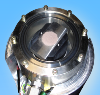
An environmental simulation chamber 'SERAC' for adsorption measurements down to -40°C was designed and built in 2007 as a complement to the reflectance spectrometer.
 Picture: SERAC simulation chamber with a mineral sample
SERAC-chamber+thermodynamic-system.JPG (TBD)
Picture: SERAC chamber connected to the thermodynamic system
Description
Reference: Pommerol et al. 2009
Sample holder
The dimensions of the sample are constrained by reflectance spectroscopy requirements (size of the incident and emergent beams and need for an infinite optical depth). The empty volume inside the chamber is 181 mL. Sample diameter is 30 mm and sample thickness can vary between 1 mm and 10 mm. According to theoretical arguments and experimental checking, sample thickness 100 times the grain size is sufficient to make negligible a potential contribution of the sample holder to the measured spectrum, even for transparent materials. Smaller thickness can be chosen when the material is not transparent over the whole spectral range measured.
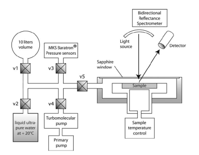
Figure: Scheme of the SERAC simulation chamber containing the sample and coupled to the spectro-gonio radiometer, and to the thermodynamic setup. Each of the five valves is numbered to be easily identified in the experimental protocol description
Optics
The simulation chamber is closed on its upper surface by a sapphire window that is 150 mm in diameter and 3 mm thick. Sapphire has excellent transmission and is spectrally featureless in the visible and near-infrared. However, light reflection on the window as well as multiple reflections between the sample and the window can affect the absolute values of reflectance measured. More problematic, multiple reflections also result in a small reduction of contrast between continuum and absorption bands in the sample reflectance spectra.
Therefore, we developed a simple model of multiple reflections between the sample and the sapphire window that we use to correct the measured spectra. In this model, we assume that when light encounters the sapphire window, a constant fraction of light, T, is transmitted in the forward direction while the complementary fraction of light, 1 - T, is reflected in the backward direction. We apply this assumption for all multiple reflections between sample and window, which gives the following relationship between the sample actual reflectance, R, and the apparent reflectance, M (measured with the window), at each wavelength:
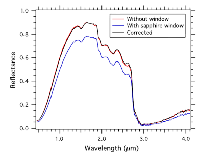
Application of this simple model to the data gives excellent results in correcting both the photometric bias and spectral effects of the sapphire window. Fig. 2 provides an example of the comparison between measurements made on the same sample without the window and with the window (raw and corrected). For this particular example, we choose an organic material that presents extremely contrasted values of reflectance in the visible and near-infrared spectral ranges to insure that the correction method is efficient from the lowest to the highest reflectance value.
Figure: Comparison between reflectance spectra of an organic material (‘‘tholin”) measured in the simulation chamber successively without (red curve) and with (blue curve) the sapphire window. Reflectance spectrum corrected from photometric and spectral effects of the sapphire window using Eq. (1) is also plotted in black.
Temperature control
The sample holder is cooled by a douvle stage Peltier elements. It can reach -30°C to -50°C depending on the external temparature (room T, or cold room down to -20°C). Temperature of the sample is adjusted and controlled using a heating resistance, a Pelletier cooling system and a PT100 Platinum resistance thermometer placed directly under the bottom of the sample. A PID controller is used to program the sample temperature (fixed, ramp, cycles. . .).
Vacuum
A turbo molecular pump is used to quickly pump the entire system to pressures lower than 10-6 mbar. A number of experiments requires an excellent static vacuum. Therefore, the whole system was optimized to avoid leaks and outgassing. When possible, only stainless steal Swagelok VCR fittings qualified for ultra vacuum were used. The only exception is the simulation chamber that is assembled with three Viton O-rings that did not present vacuum performance satisfactory for our purpose. Therefore we doubled every Viton O-ring to permit an active pumping between the two concentric O-rings (classical ‘‘double O-ring” high vacuum fitting). Using this procedure and after consequent outgassing at high temperature and secondary vacuum, it is possible to obtain a high quality static vacuum (<10-6 mbar) that can be maintained in a close system at least for a few weeks.
Pressure sensors
A MKS Baratron absolute pressure sensor (range: 1 Torr) to monitor pressure inside the chamber. This particular sensor is able to measure pressure between 10-6 and 1 mbar. Relative uncertainty on the recorded value is highly dependant on pressure range: 50% at 10-5 mbar, 5% at 10-4 mbar, 0.5% at 10-3 mbar, 0.1% at 10-2 mbar and less than 0.1% at higher pressure.
Sample dehydration procedure
Prior to measurements the sample, sample holder and walls of the simulation chamber can be dehydrated by maintaining them at high temperature (70–170°C) under secondary vacuum during several hours to evacuate water and other trapped gases.
procedure exemple
The sample holder filled with a mineral powder is placed in the simulation chamber. The dehydration process is divided into successive steps that aim to remove the maximum amount of moisture from the sample while avoiding deterioration of its surface flatness (volume change and dehydration cracking).
- First, the sample is heated at 170°C following a temperature ramp of 1 h while the chamber is still open to air.
- After 1 h of heating at 170°C, the chamber is closed and heating stops. Sample temperature decreases for a few hours to reach the temperature of the cold room (0 to -20°C).
- Then, the simulation chamber is slowly pumped down to pressure lower than 10-6 mbar.
- Under secondary vacuum, the sample is heated again at 170°C during a minimum of 10 h. In the same time, the chamber itself and fittings are heated using heating cords to ensure a quick and efficient outgassing.
- Finally, the sample is cooled to the temperature at which measurements are performed and temperature is then kept constant (±0.1°C) for the complete set of measurements.


